Flang Types
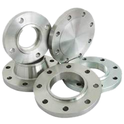 ANSI FLANGES
Most forged steel flanges correspond to the requirements of the American Standards Association (ASME/ANSI Standard B16.5) and the ASTM Specification A-105.
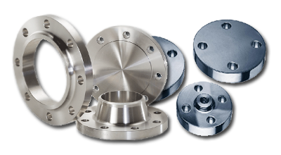
The following types are manufactured and stocked:
Welding Neck Flanges: Are available in all pressure ratings and sizes, are butt-welded to the end of the pipe, and are usually specified when service conditions are severe and excellent workmanship necessary. Since the inside diameter of the flange must match that of the pipe, the flange bore should be specified in ordering.
Slip-on Flanges: Are available in most pressure ratings and sizes, are a popular type due to their ease of application. This permits double-welding of the flange - one strength fillet weld to join the hub of the flange to the pipe, and a seal fillet weld inside the flange at the end of the pipe. Where operating conditions permit, the seal weld is omitted. Slip-on flanges are most frequently used at lower pressure - Class 150 (PN 20) or Class 300 (PN 50) primary service pressure ratings. Many pipe designers are reluctant to use slip-ons for higher pressures, since (1) the joint between the flange and pipe is not as strong as in the welding neck type; and (2) the junction of the flange and pipe is more susceptible to corrosion.
Screwed or Threaded Flanges: Are attached to the pipe like any other screwed fittings, and may be back-welded to seal the joint between pipe and flange. Although still available in most sizes and pressure ratings, screwed fittings today are used almost exclusively in smaller pipe sizes and at low pressures.
Lap Joint or Van Stone Flanges: Are used on piping equipped with lap joint stub ends or with lapped pipe. They may be used at all pressures and are available in a full size range. These flanges slip over the pipe, and are not welded or otherwise fastened to it; bolting pressure is transmitted to the gasket by the pressure of the flange against the back of the pipe lap.
Lap Joint flanges have certain special advantages:
(1) freedom to swivel around the pipe facilitates the lining up of opposing flange bolt holes;
(2) lack of contact with the fluid in the pipe often permits the use of inexpensive carbon steel flanges with corrosion resistant pipe or tubing;
(3) in systems which erode or corrode quickly, the flanges may be salvaged for re-use.
Socket-welding flanges contain a recess in the back of the flange to receive the end of the pipe, which is attached by a fillet weld around the hub of the flange. Since socket-welding connections are not as strong as butt-welded joints, the use of this type of flange is almost always confined to NPS 4 (DN 100) and smaller sizes, and to the lower pressure ratings. Its chief advantage lies in the ease of preparation and installation.
Blind Flanges: Are available in all sizes and pressure ratings, are solid forgings used to close off the end of a piping system and to gain easy access to the interior of the line. Reducing flanges are available. Refer to page 18.
FLANGE FACINGS
Unless otherwise specified, Class 150 (PN 20) and Class 300 (PN 50) flanges in all types except lap joint (or Van Stone) flanges are furnished with a .06" (1.6mm) raised face (which is included in the flange thickness dimension). Heaver pressure ratings are machined with a .25" (6.4 mm) raised face, in addition to the designated flange thickness.
When so ordered, these flange types can be furnished with a variety of other facings, such as male and female, ring joint, tongue and groove, etc. Lap Joint flanges are machined with a flat face and a fillet radius to accommodate the stub end or pipe lap.
FLANGE FINISHES
The finish of contact faces of pipe flanges and connecting end flanges of fittings shall be judged by visual comparison with AARH
Standards and not by instruments having stylus tracers and electronic amplification (see ANSI/ASME B46.1)
The finishes required are given below. Other finishes may be furnished upon application.
RAISED FACE AND LARGE MALE AND FEMALE: Either a serrated-concentric or serrated-spiral finish having from 45 to 55
grooves per inch (0.6 to 1mm pitch) shall be used. The cutting tool employed shall have an approximate 0.06" (1.6mm) or larger radius. The resultant surface shall have a 125 to 250 micro inch roughness.
TONGUE AND GROOVE AND SMALL MALE AND FEMALE: The gasket contact shall not exceed 125 micro inch roughness.
RING JOINT: The side wall surface of gasket groove shall not exceed 63 micro inch roughness.
MATERIAL AND MANUFACTURING STANDARDS
 The manufacturing of forged steel flanges is governed by industry standards written by (1) the American Society for Testing and Materials (ASTM); (2) the American National Standards Institute (ANSI); (3) the Manufacturer’s Standardization Society of the Valve and Fittings Industry (MSS); (4) the American Petroleum Institute (API); (5) the Canadian Standards Association (CSA); (6) the American Society of Mechanical Engineers (ASME); and (7) the Pipe Fabrication Institute (PFI). They cover specifications for materials, methods of manufacture, dimensions and quality control procedures. CCTF forged steel flanges conform to all applicable standards.
ASTM SPECIFICATIONS
ASTM specifications are, basically, materials specifications. They regulate approved raw materials from which flanges can be
made - ingots, or blooms, billets, slabs or bars. In addition, they govern the methods of manufacture, quality control procedures and markings of forged steel flanges. ASTM specifications are divided into five categories:
- A105 - Carbon grades for high temperature service
- A181 - Carbon grades for general service
- A182 - Alloy and stainless grades for high temperature service
- A350 - Carbon and alloy grades for low temperature service
*CCTF flanges are available in a wide range of alloy and stainless steels, including grades F304, F304L, F316, F316L. Please
refer to CCTF catalogue “Stainless Steel Flanges” for the popular Classes 150 and 300 (PN 20 and 50).
MSS, API, AWWA, ANSI AND CSA STANDARDS
ANSI, MSS and API standards govern flange dimensions and tolerances. ASME/ANSI B16.5, titled “Steel Pipe Flanges and
Flanged Fittings”, is the basic standard. It covers forged steel flanges, sizes NPS 1/2 (DN 15) through NPS 24 (DN 600). CSA
standard CAN3-Z245 12-M96 covers the manufacture, dimensions, tolerances and material requirements for pipe line flanges.
ASME/ANSI B16.36 covers Orifice flanges. The following MSS, API and AWWA standards are written to supplement B16.5:
- MSS SP-6: Flange facings
- MSS SP-9: Spot facing for bronze, iron and steel flanges
- MSS SP-25: Marking of flanges
- MSS SP-39: Bolts and nuts for flanges
- API6A: Wellhead equipment
- AWWA C207: Hub flanges
The following codes are not flange specifications, but they influences the manufacture of forged steel flanges:
- ASME: Boiler and Pressure Vessel Code
- ASME/ANSI B31.1: Power Piping
- ASME/ANSI B31.3: Petroleum and refinery piping
- ASME/ANSI B31.4: Liquid petroleum transportation piping systems
- ASME/ANSI B31.5: Refrigeration piping
- ASME/ANSI B31.8: Gas transmission and distribution piping systems
- ANSI/ASME B36.10M: Standard for wrought steel pipe
- ANSI/ASME B36.19M: Standard for stainless steel pipe
- ANSI/ASME B16.47: Large diameter pipe line flanges NPS 22 (DN 550) and NPS 26 (DN 650) through NPS 36 (DN900)
METRIC EQUIVALENTS
The International System (SI) metric equivalent of British units are shown throughout this catalogue.
NPS (Nominal Pipe Size) = DN* (Nominal Diameter)
Operating Pressure Class = PN* (Pressure Number)
1 inch = 25.4 milli metres
1 pound, weight = 0.4536 kilograms
1 pound, pressure = 0.06895 bars
1 p.s.i., stress = 0.006895 megapascals (MPa)
*From the SI designations, Diamètre Nominal and Pression Nominale.